Maximum Aluminum: Optimizing Metal Removal Rate in Aluminum with a High Speed Spindle
Speed changes the rules. To maximize metal removal rate with a high speed spindle, follow some fundamental tooling considerations and mill at just the right rpm.
Share


Hwacheon Machinery America, Inc.
Featured Content
View More
Takumi USA
Featured Content
View More


Autodesk, Inc.
Featured Content
View MoreAluminum is among the easiest metals to machine. And today, that's what makes machining it competitively a challenge.
Faster spindle speeds affect all metal cutting applications, but speed changes the rules for aluminum more than it does for other metals. In steels and harder alloys, the higher speed is combined with a light depth of cut, leaving the fundamental limits on the process unchanged. Maximum metal removal rate is still set by the performance limits of the tooling and the machine.
Aluminum, however, is unique among the most commonly machined metals in that the high spindle speed is often combined with heavy cuts. This combination—speed plus depth—makes chatter a far more significant concern. As a result, the shop hogging aluminum at high spindle speed faces not two process limits, but three. There are the machine and tool limitations just like always, and now there is also the limiting effect imposed by the harmonic characteristics of the spindle and tooling system overall.
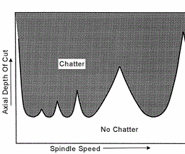
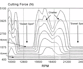
The primary result of these harmonic effects is that the top speed is no longer the best speed as far as metal removal rate is concerned. Instead, any milling process run at around 15,000 rpm or higher is likely to offer some optimum spindle speed, a "sweet spot," where the cut is significantly more stable than it is at both higher and lower speed settings. This sweet spot rpm value may permit double the depth of cut compared to other speeds. It may permit triple the depth of cut. That's why effective high speed machining of aluminum calls for a type of knowledge—basic vibration analysis—the shop may never have needed before.
This article is about how to perform that analysis.
The payback—a higher metal removal rate in aluminum—has never been more valuable. Speed doesn't just change the rules for effective milling, it also increases the very demand for this milling work. Today's freedom to machine aluminum faster has allowed many costly assemblies in aircraft frames to be replaced economically with sophisticated structures machined in one piece out of aluminum billet. In many cases, better than 90 percent of the original stock gets turned into chips to make these parts. That's why a high metal removal rate is so beneficial.
One machine tool builder that has a vested interest in helping shops achieve these high metal removal rates is Cincinnati Machine. The Cincinnati, Ohio, builder offers a range of high speed machine tools for aluminum milling. At the far end of this range is the company's newly introduced "Hypermach" line of high speed horizontal machines for large aircraft parts. Linear motors give Hypermach models high feed rate and high linear acceleration. Spindle options include a model offering 100 hp and 24,000 rpm. To win the most effectiveness from this and other higher-end machines, finding the right speed for each application is key.
Among the Cincinnati Machine employees who assist customers with this work is principal engineer Sinan Badrawy, source for much of this article. Dr. Badrawy is one of a group he calls the "dynamic mafia," a small number of metalworking industry researchers (most affiliated with the University of Florida at one time or another) who study dynamic vibration analysis specifically as it applies to machining. Tools commonly employed in this research include a sensitive hammer for "ringing" the spindle like a bell, coupled with electronic sensors for mapping the vibrations that result. Mathematical tools for analyzing these vibrations include numbers so far removed from the numbers you and I count with that they are called—literally—imaginary numbers.
But Dr. Badrawy insists that diagnosing a machining center's sweet spots can be done without any of these tools, and without a degree in dynamics.
For example, there is software available today that can calculate the optimum spindle speed for a process just by listening to chatter across a microphone linked to the PC. This software, combined with some test cutting, can uncover the ideal machining parameters.
However, just test cutting alone can also be enough. A shop can find optimum spindle speeds and depths of cut using resources it already has available. Probably the most expensive investment will be time on the machine.
The first step, says Dr. Badrawy, is to understand something about the nature of this optimum spindle speed you're after.
Chatter Unmasked
You may think chatter in milling is entirely the product of cutting edges hitting the workpiece—in other words, bang bang bang, and chatter comes from this.
The image is partly correct, but it misses something fundamental. The "bang bang bang" describes a forced vibration. Chatter, on the other hand, is a self-excited vibration.
What's the difference? The same as the difference between a guitar and a violin. A guitar's sound comes directly from a single impulse, that of a finger plucking the string. But a violin's sound is a continuous tone that feeds on friction. A bow passes over the string, and the sound grows out of the harmonic resonance that results.
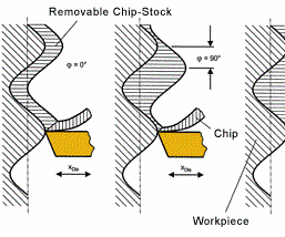
In the same way, chatter in machining is not a result of "plucking" from the cutting edges, but is instead a result of the continuous interaction between these impacts and the surface that has already been machined. That previously machined surface has waviness in it resulting from the previous pass. Even if the surface looks mirror smooth, the waviness is there. Vibration from cutting edges hitting the workpiece is one component of chatter, and this waviness is the other.
The sweet spot is a speed at which these two components harmonize. Chatter is at its worst when the opposite is true—when vibration from the cutting edges moves as the mirror image of surface waviness. (See the diagram) In the language of vibration analysis, this condition is "180 degrees out of phase." The ideal condition (also shown in the diagram) is when the waviness and cutting vibration are perfectly in phase. At this speed, the load is constant, the cut is smooth, and the tool can take a much deeper cut without adverse effects. Truly, this is a sweet spot at which to mill.
Where Chatter Matters
Not every aluminum milling process, even at high speeds and even at high depths of cut, will feature a sweet spot that is so strikingly superior. There are at least three cases in which the search for a sweet spot may not be necessary.
The first two cases have already been alluded to. One is when spindle rpm is very low. Exactly how low will differ from process to process, but at the early end of the speed range, natural process damping will be strong enough to smother chatter before it starts.
Another case is when depth of cut is light—say, 0.050 inch and below. Chatter isn't significant where cutting forces are low.
The final case where the search for a sweet spot may not be necessary is when everything about the process is very stiff. That is, the workholding is rigid, the spindle has a high dynamic stiffness and a secure hold on the toolholder, the toolholder itself is compact, and the cutting tool is very short. When all of these conditions are met, chatter may not play a major role, and the top speed may indeed be the best speed.
The problem is, large aircraft structural components often don't offer the luxury of using the shortest available tooling. A deep pocket may demand a longer reach, and a tool tip that extends farther from the spindle will whip farther if chatter sets in. Perhaps the main reason why finding the sweet spot permits such large process improvements in aircraft machining work is that these parts typically call for tooling that is less than ideally rigid.
The Case For Cutting
One interesting trait of chatter is that the sound of a single cut taken at some speed where chatter occurs can contain enough mathematical information to determine what the stable cutting speed would be. Accordingly, there are software tools and analyzers that use a microphone to listen to the cut, then calculate optimum spindle speeds based on this input. (For information on two such products, refer to the “Learn More” near the top of this page.)
Another way to "predict" the optimum speed is through the hammer test that specialists such as Dr. Badrawy perform. This test requires no cutting at all. However, it does require an understanding of vibration analysis unavailable in most shops.
Cutting tests, on the other hand, rely on knowledge that any shop hogging aluminum already possesses—how to take a milling pass, and what chatter looks and sounds like.
A fair amount of cutting may be required, however. The following point can't be overstressed: Harmonic characteristics are not inherent to the spindle and not inherent to the machine . . . but instead are characteristic of the entire system of spindle + toolholder + tool + tool gage length. Change any one of these components, and you have a different system for which different optimum cutting parameters will have to be found.
As a result, every different tool design will demand its own analysis.
That means you may be using too many tools. If you intend to take full advantage of harmonic sweet spots in your own aluminum milling process, it may be necessary to cut back on the range of tools available, just to limit the amount of testing required.
That was certainly the case within a Boeing facility that committed to running at harmonically optimized speeds. Programmers sending work to this shop once chose tools according to their individual preferences. Taking advantage of the sweet spots required them instead to choose tools from a common list. This was the list of all combinations of tool, toolholder and spindle for which the sweet spot had been found.
Your own testing should record this same information. Record the spindle used, for example. Shops with redundant machines get a break here because identical machines with identical spindles can be expected to have identical (or at least similar enough) harmonic characteristics.
Also record the specific tool and toolholder style, as well as the length to which the tool is clamped if it's possible for this length to vary.
The information you are about learn will only apply when you put this same combination together again.
Here's how to find the optimum cutting parameters for this particular system:
Procedures
The maximum spindle speed is as good a starting point as any, so mill a pass at top speed.
Chip load doesn't matter. For actual production machining, the choice of chip load is very significant (see Chip Load, below), but because chip load doesn't influence harmonic effects, any reasonable value will do during testing so long as the same chip load is used for every cut.
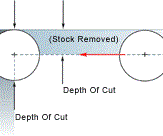
For radial depth of cut, pick an arbitrary value that will remain constant until the sweet spot is found—50 percent of cutter diameter, for example.
For axial depth of cut, start light and keep increasing until chatter sets in. For example, start at 0.10 inch, and if there is no chatter at this axial depth, take passes at 0.15, 0.20, and so on until chatter occurs.
For the maximum depth achieved prior to chatter, compute the metal removal rate. MRR equals feed rate × axial depth of cut × radial depth of cut.
It may also be useful to note the spindle load. MRR and spindle load will help you compare the best the machine was able to do at this speed with the best it can do at other speeds.
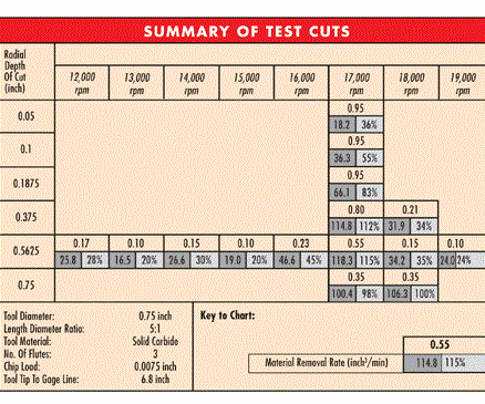
Now, reduce spindle speed by 1,000 rpm and follow the same procedure again. The machine may perform better at this speed, or it may perform worse. In either case, at the maximum chatter-free axial depth, record MRR and spindle load again.
As you keep testing, likely you will find some spindle speed at which it's possible to take much deeper cuts without chatter. You know you have found a sweet spot if performance is significantly better at this speed than the performance at speeds both 1,000 rpm faster and 1,000 rpm slower. This sweet spot is probably—but not certainly—the speed at which you want to machine.
Check the metal removal rates to be sure. The speed that gives the best MRR is the speed at which you want to run.
Now it's time to vary the radial depth of cut. At the chosen speed, run at a variety of radial depths to simulate the different types of cuts this tool might take. A good mix might be to run at 25, 50 and 100 percent of cutter diameter—representing finishing, roughing and slotting cuts, respectively. Every radial depth will permit a different axial depth. Perform test cutting to determine the maximum stable axial depth for each one.
The testing is now finished for this system. Armed with these data, programmers can know exactly what speed and exactly what depths of cut to specify whenever they call for this combination of machine, toolholder and cutting tool.
Life And Load
A software tool or analyzer that can zero in on the right spindle speed can save the time and material necessary to hunt for this speed by counting down to it from the top of the speed range. However, even with the analyzer, it's still necessary to perform test cuts at various depths to determine how deep the machine can cut at this speed.
This part of the testing—taking deeper and deeper cuts—is where keeping an eye on spindle load may be important. Within a harmonic sweet spot, the cut may be stable enough to mill chatter-free even to a depth where the spindle can no longer handle the load.
In other words, when sweet spot machining moves the chatter barrier out of the way, the barriers that remain are the machine and tool limits that shops working at lower speeds have faced all along.
Different machine tool users have different opinions as to what spindle load the process should be allowed to see. In a stable process, Dr. Badrawy believes the spindle can be allowed to run continuously at a load as high as 80 percent. He knows shops, however, that prefer to run no higher than 50 percent out of consideration for the spindle life. This may be too conservative, he says. Chatter and other sources of rapidly varying load are what cause spindles to fail prematurely. A steady load—even if the load is heavy—shouldn't impair the spindle's life, he says.
In fact, the difference in spindle life between high-chatter and low-chatter cutting can be striking. He once deliberately ran a high speed spindle in high-chatter conditions just to see how long it would hold up. He got it to fail in only three hours. By contrast, in processes run at harmonically optimized conditions, he has seen little enough effect on the spindle that he questions the very notion that high speed machining has to turn the spindle into a disposable commodity. Running at high rpm does accelerate the life cycle, but not as much as the replacement frequency in some shops would suggest. With chatter under control, he says, a quality spindle used in production high speed milling can last 3 to 5 years.
Related Content
Shop Replaces Two Verticals With One Horizontal
By trading two VMCs in to help finance the purchase of a new HMC, this shop was able to significantly increase production and move to lights-out machining.
Read MoreGrob Robot Cell Enables Long Periods of Unmanned Operation
The GRC-R12 robot cell features a pneumatic single- or double-gripper system, as well as a drawer feed system with six drawers.
Read MoreFour-Axis Horizontal Machining Doubles Shop’s Productivity
Horizontal four-axis machining enabled McKenzie CNC to cut operations and cycle times for its high-mix, high-repeat work — more than doubling its throughput.
Read MoreDN Solutions America Unveils Impressive Chicago Technical Center at IMTS 2024
New tech center is serving as a cutting-edge showroom and a technological hub for advanced machining applications.
Read MoreRead Next
Building Out a Foundation for Student Machinists
Autodesk and Haas have teamed up to produce an introductory course for students that covers the basics of CAD, CAM and CNC while providing them with a portfolio part.
Read MoreRegistration Now Open for the Precision Machining Technology Show (PMTS) 2025
The precision machining industry’s premier event returns to Cleveland, OH, April 1-3.
Read More


.png;maxWidth=150)





.jpg;maxWidth=300;quality=90)


